
| On-screen output |
Checkpoints to LPT ports |
Checkpoints to COM1 |
Checkpoints to 80h |
Speaker beep |
IBM 5150 relay click |
Comment | |
|---|---|---|---|---|---|---|---|
| Option #1: MDA video card | Yes | Yes | Yes | Yes | Yes | Yes | |
| Option #2: CGA video card | Yes | Yes | Yes | Yes | Yes | Yes | |
| Option #3: 4KB RAM at address A0000 | No | Yes | Yes | Yes | Yes | Yes | |
| Option #4: 4KB RAM at address B0000 | No | Yes | Yes | Yes | Yes | Yes | The diagnostic will think that you have an MDA video card. |
| Option #5: 4KB RAM at address B8000 | No | Yes | Yes | Yes | Yes | Yes | The diagnostic will think that you have a CGA video card. |
| Option #6: None of the above | No | Limited | Limited | Limited | Yes | Yes |
| 1. | The 'Hot NMI' test is known to fail if either: - Math coprocessor (8087 chip) is absent and you have switch 2 in switch block SW1 in the wrong position for that (off). - Math coprocessor (8087 chip) is present and is faulty in a particular way. |
|||
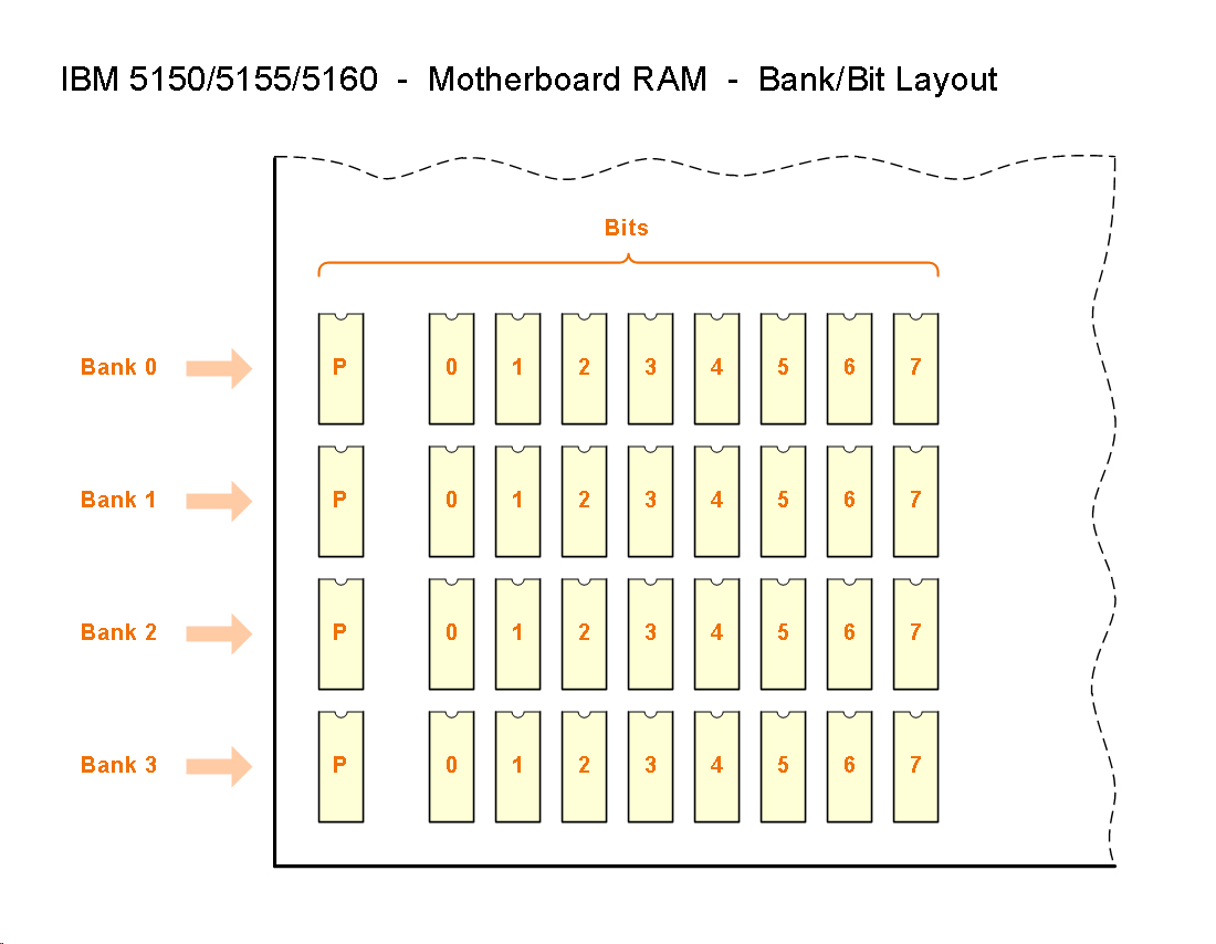
| 2. | If there is a faulty RAM chip for parity, it will not be shown until all faulty RAM chip/s for data (in the same bank) have been rectified. | |||
| 3. | The 'Check ROM at F4000' test is expected to fail, because there is nothing in the motherboard's U28 socket. However, on some IBM 5150 motherboards, the test might pass. You may even see it pass sometimes, and fail at other times. |
| Condition | Observed behaviour | Comment |
|---|---|---|
| All 4 banks are good | See the partial screen shot at here. | 4 banks of 16 KB = 64 KB |
| Only bank 0 is populated, and all chips in it are good | See the partial screen shot at here. | 1 bank of 16 KB = 16 KB |
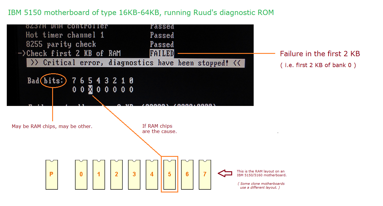
| A single chip has failed, in bank 0. Failure affects the first 2K of addresses. |
See the partial screen shot at here. | • Includes a complete failure of chip (i.e. affecting all addresses in chip). See note 1 below. |
A single chip has failed, in bank 0. Failure is after the first 2K of addresses. |
The 'Testing RAM - Data' test fails. Under that is: • "Failure at address: xx KB" is displayed, where 'xx' is a figure between 2 KB and 15 KB. • The bad bit is displayed (example at here). |
• 16KB-64KB motherboard. |
A single chip has failed, in bank 1 |
The 'Testing RAM - Data' test fails. Under that is: • "Failure at address: xx KB" is displayed, where 'xx' is a figure between 16 KB and 31 KB. • The bad bit is displayed (example at here). |
• 16KB-64KB motherboard. • A figure between 17 KB and 31 KB is due to note 4. |
A single chip has failed, in bank 2 |
The 'Testing RAM - Data' test fails. Under that is: • "Failure at address: xx KB" is displayed, where 'xx' is a figure between 32 KB and 47 KB. • The bad bit is displayed (example at here). |
• 16KB-64KB motherboard. • A figure between 33 KB and 47 KB is due to note 4. |
A single chip has failed, in bank 3 |
The 'Testing RAM - Data' test fails. Under that is: • "Failure at address: xx KB" is displayed, where 'xx' is a figure between 48 KB and 63 KB. • The bad bit is displayed (example at here). |
• 16KB-64KB motherboard. • A figure between 49 KB and 63 KB is due to note 4. |
| Type of EPROM for IBM 5150 | Size | Image download | Photo | Comment |
|---|---|---|---|---|
| MCM68766 EPROM | 8 KB | Download | ||
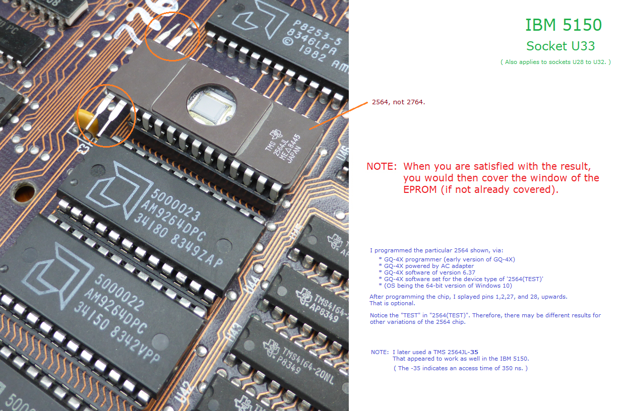
| 2564 EPROM | 8 KB | Download | Photo | 2564, not 2764 |
| With adapter, 2764/27C64 EPROM | 8 KB | Download | Click here for adapter. | |
| With adapter, 27128/27C128 EPROM | 16 KB | Download | Click here for adapter. See note 2 below. | |
| With adapter, 27256/27C256 EPROM | 32 KB | Download | Photo | Click here for adapter. See note 2 below. |
| With adapter, W27E257 EEPROM | 32 KB | Download | Click here for adapter. See notes 2 and 3 below. |
| Note 1 | It is possible for a RAM chip to fail in such a way that affects only some of the chip's addresses. Imagine such a chip in bank 0, one that fails at say the 5K address. That would result in the diagnostics 'Check first 2 KB of RAM' test passing. But the diagnostic will report an error later when testing the remainder of RAM. |
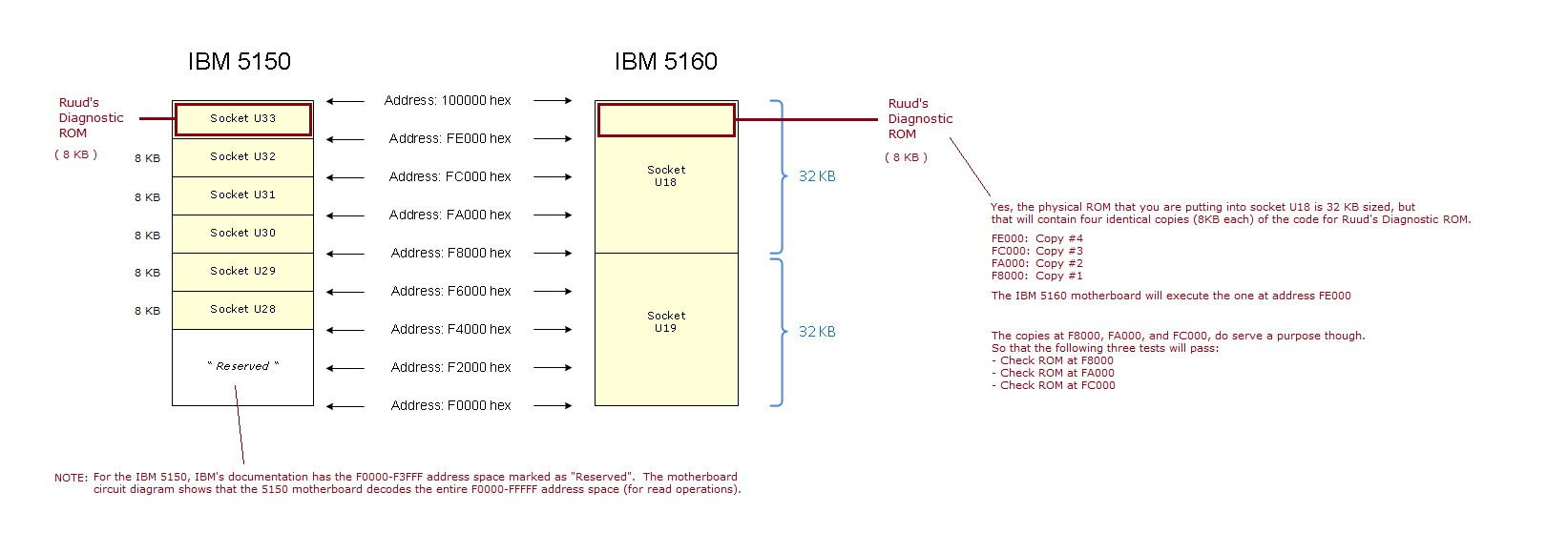
| Note 2 | Ruud's Diagnostic ROM for the PC and XT is actually only 8 KB in size. To create a 16 KB sized image, the 8 KB image was simply doubled. To create a 32 KB sized image, the 8 KB image was simply quadrupled. A related diagram is at here. |
| Note 3 | Regarding the programming/writing of an image into the W27E257: Even though the W27E257 is an EEPROM, rather than a 'traditional' EPROM, you will still need an EPROM programmer (or other) to program/write to the W27E257. That is because the IBM 5150 motherboard does not support programming/writing to EEPROM's in its sockets. |
| Note 4 | It is possible for a RAM chip to fail in such a way that not all of its addresses are affected by the failure. |
| Note 5 | For most of its work, Ruud's Diagnostic ROM (RDR) needs some RAM for variables and for the stack. The motherboard RAM cannot be trusted (a common use of RDR being because there is bad RAM in bank 0). For that reason, RDR uses either: - If an MDA video card is present, the unused video RAM on that; or - If an CGA video card is present, the unused video RAM on that; or - If 4 KB of RAM at address A0000, some of that RAM. (Version 4.3 or later of RDR required.) - If 4 KB of RAM at address B0000, some of that RAM. - If 4 KB of RAM at address B8000, some of that RAM. |