 |
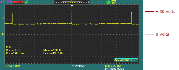
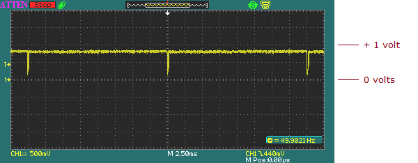
Vertical sync pulses out of IBM MDA card.
|
| |
|
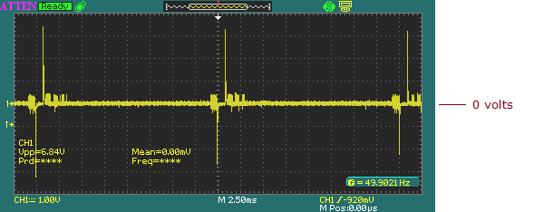 |
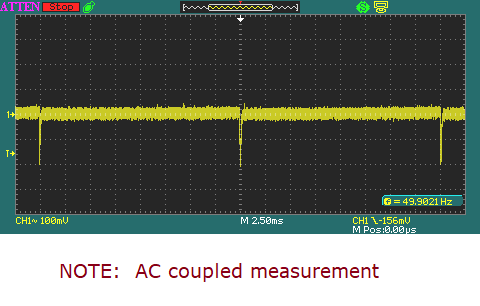
Cathode of diode D401.
( Vertical sync pulses differentiated to become positive and negative spikes. )
|
| |
|
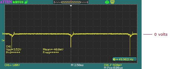 |
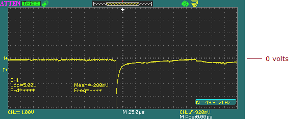
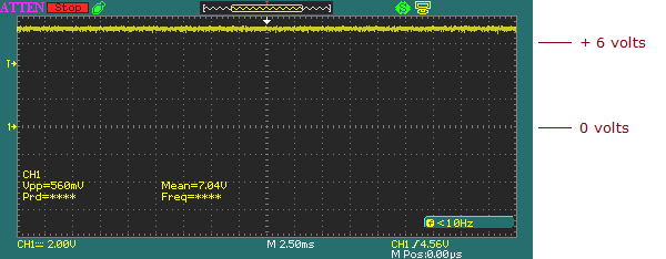
Anode of diode D401.
( Positive spikes removed. )
( Time expanded version follows. )
|
| |
|
 |
|
| |
|
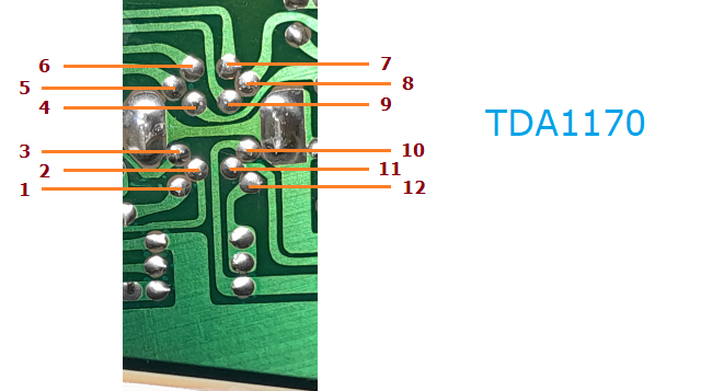 |
TDA1170N
Pin numbering on solder side of PCB.
|
| |
|
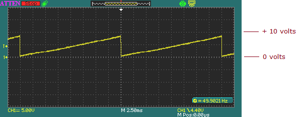 |
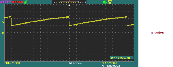
Pin 1 of TDA1170N.
( RAMP OUTPUT )
Vert. Size potentiometer changes ramp height.
Vert. Linearity potentiometer changes linearity of ramp slope.
|
| |
|
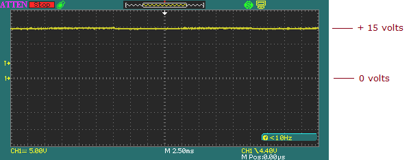 |
Pin 2 of TDA1170N.
( SUPPLY VOLTAGE )
About +15V
|
| |
|
 |
Pin 3 of TDA1170N.
( FLYBACK )
|
| |
|
 |
Pin 4 of TDA1170N.
( AMP. OUTPUT )
What heads to the vertical deflection coils.
|
| |
|
 |
Pin 5 of TDA1170N.
( AMP. VOLTAGE )
|
| |
|
 |
Pin 6 of TDA1170N.
( REGULATED VOLTAGE )
|
| |
|
 |
Pin 7 of TDA1170N.
( HEIGHT ADJUST )
I did not see a noticeable change in the waveform when adjusting the Vert. Size potentiometer.
|
| |
|
 |
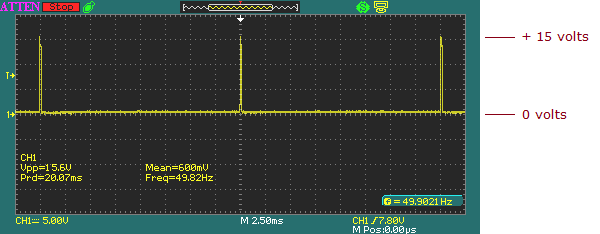
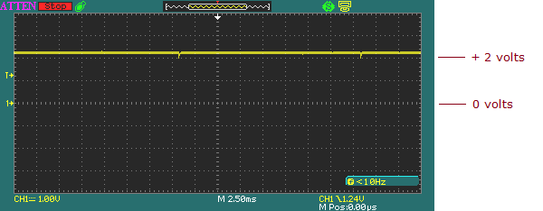
Pin 8 of TDA1170N.
( SYNC. INPUT )
NOTE: Only hundreds of mV.
|
| |
|
 |
Pin 9 of TDA1170N.
( OSCILLATOR )
|
| |
|
 |
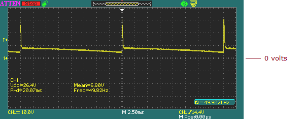
Pin 10 of TDA1170N.
( AMP. INPUT )
Per here, those small pulses are about 200 mV in amplitude.
I was expecting a noticable ramp waveform.
|
| |
|
 |
Pin 11 of TDA1170N.
( COMPENSATION )
|
| |
|
 |
Pin 12 of TDA1170N.
( RAMP GENERATOR )
|
| |
|
