

| Parent |
| IMPORTANT: | The following is specific to the IBM 5160 (IBM XT), fitted with IBM BIOS ROM's. |
| • | The IBM 5160's POST will go into TEST CHAMBER mode if it finds that switch 1 on the motherboard's switch block SW1 is set to ON. |
| • | To the user, the obvious consequence of TEST CHAMBER mode is that the POST runs in a loop (when the POST finishes, it restarts rather than attempting to boot from something). |
| • | In TEST CHAMBER mode, the POST's keyboard test (301 test) is skipped. |
| • | In TEST CHAMBER mode, the POST's diskette test (601 test) is skipped. |
| • | The IBM 5160's POST will go into MANUFACTURING TEST mode if it finds that the motherboard's keyboard data line ('KBD DATA') is at a TTL LOW state (or is grounded). 'Back in the day', IBM would have used some kind of test kit to put a TTL LOW on the keyboard data line (or ground that line). An example of how to do that using a DIN plug, is shown at here. Certain faults can result in the POST going into MANUFACTURING TEST mode: - A keyboard (or keyboard adapter) that is faulty in a way that drives the keyboard data line to a permanent LOW (or somehow grounds the line); - The motherboard's keyboard interface circuitry is faulty in a particular way.  |
| • | In MANUFACTURING TEST mode, the POST's keyboard test (301 test) is skipped. |
| • | In MANUFACTURING TEST mode, the single short beep of the speaker done near the end of the POST is skipped. |
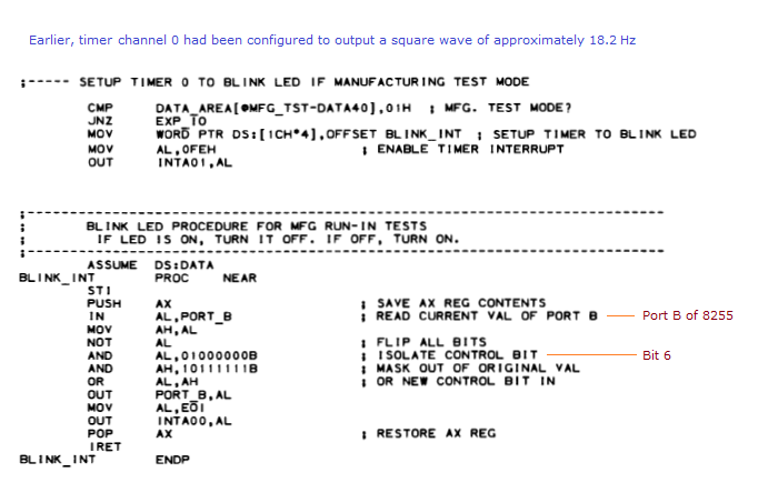
| • | In MANUFACTURING TEST mode, the POST gets channel #0 on the 8253 timer chip to trigger a "BLINK LED" operation. Earlier, channel 0 of the 8253 timer was set to output a square wave of about 18.2 Hz, so, at about 18.2 Hz, a subroutine ("BLINK_INT") is run that toggles the PB6 pin (bit 6 of port B) of the 8255 chip. Per here, the PB6 pin going LOW pulls the keyboard clock line ('KBD CLK') on the motherboard's keyboard DIN connector to LOW. The result is a square wave of about 9.1 Hz on the keyboard clock line on the motherboard's keyboard DIN connector. So, presumably, for MANUFACTURING TEST mode, IBM plugged a custom device into the motherboard's keyboard DIN connector. The device: - Grounds the keyboard data line ('KBD DATA'), so as to put the POST into MANUFACTURING TEST mode; and - Has a LED connected between ground and the keyboard clock line ('KBD CLK'). My homemade device, which includes the LED, is shown at here. It has been observed that blinking of the LED will not happen if the POST declares a video card error (1 long beep then 2 short beeps when there is nothing plugged into the motherboard's keyboard DIN connector). If you are in that situation, set the two video switches on the motherboard to the EGA setting.  |