IMPORTANT: |
The third column in the table below contains the word, "SOME". |
| TEST / ACTION | DESCRIPTION | SOME POSSIBLE FAILURE CAUSES |
|---|---|---|
| "Testing CPU" | Mainly testing the branch instructions and registers of the CPU. | • Bad CPU. • Corrupt/damaged Rudd's Diagnostic ROM. • Faulty data path in direction of ROM --> CPU. (E.g. stuck bit.) • Addressing problem. |
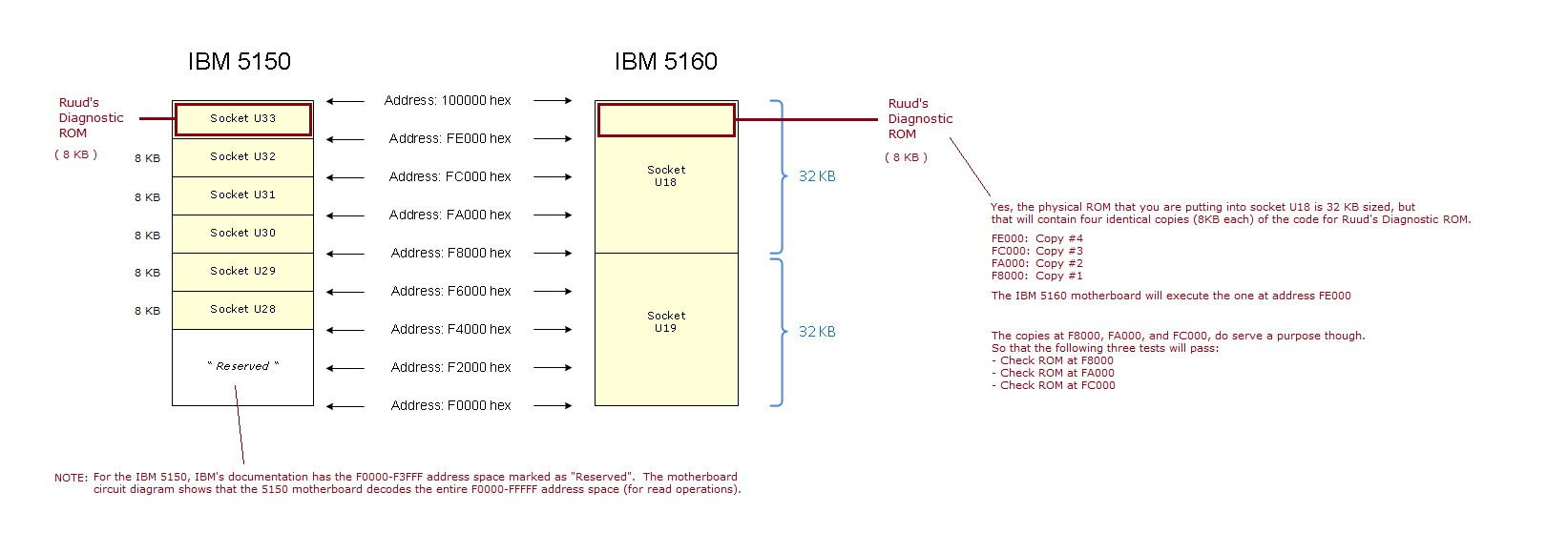
| "Diagnostic ROM checksum" | A reference diagram is at here. Ruud's Diagnostic ROM sits in the 8 KB sized memory space of FE000 to FFFFF. What this test does is read all of the bytes in that memory space, and add them together to create an 8-bit checksum. The tests passes if the 8-bit checksum is 00. | • Corrupt/damaged Rudd's Diagnostic ROM. • Faulty data path in direction of ROM --> CPU. See note 2 below. • Addressing problem. |
| Beep the speaker three times: short-long-short. |
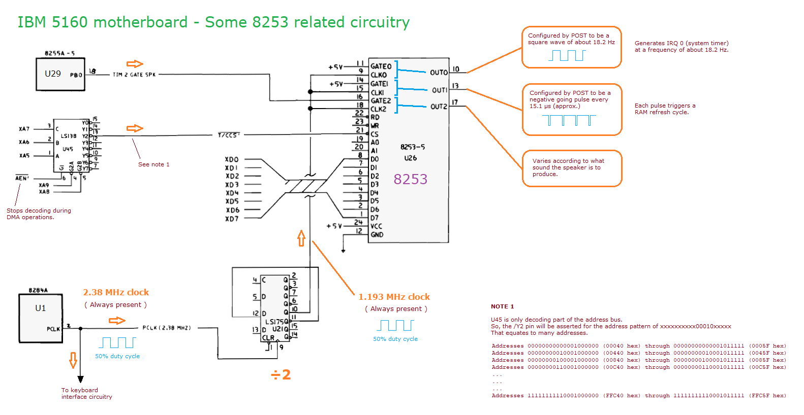
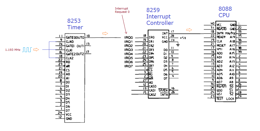
Reference diagrams are at: IBM 5150: here and here. IBM 5160: here and here. This test programs the 8255 and 8253 chips in a way that results in the beeps. Other circuitry is involved. This is the first test/action that tests I/O writes (i.e. beeping means the I/O writes must be working). |
• Faulty circuitry, that shown in the first reference diagram. • Missing 1.193 MHz clock for the 8253 timer chip. • Faulty support chips. See note 1 below. |
| "8253 timer channel 0" | Test channel 0 of the 8253 timer chip. Mode 2 only. Verify that it is counting as expected. | • Faulty 8253 timer chip. • Faulty chip that supports 8253 operation. See note 1 below. |
| "8253 timer channel 1" | Test channel 1 of the 8253 timer chip. Mode 2 only. Verify that it is counting as expected. | • Faulty 8253 timer chip. • Faulty chip that supports 8253 operation. See note 1 below. |
| "8253 timer channel 2" | Test channel 2 of the 8253 timer chip. Mode 2 only. Verify that it is counting as expected. | • Faulty 8253 timer chip. • Faulty chip that supports 8253 operation. See note 1 below. |
| "8237A DMA controller" | Does a read/write test of the first 8 registers of the 8237A DMA controller chip. Note that this is barely testing the 8237A. |
• Faulty 8237A DMA controller chip. • Faulty chip that supports 8237A operation. See note 1 below. |
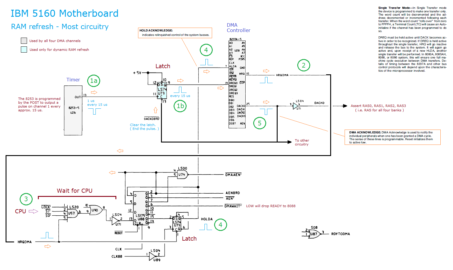
| "Hot timer channel 1" | Reference diagrams are at: IBM 5150: here. IBM 5160: here. This test interogates the 8237A DMA controller chip to discover whether the controller's 'DREQ 0' pin (pin 19) is HIGH or LOW. At this time, the pin should be LOW. If found HIGH, there is a problem, and the test is failed. |
• Faulty 8237A DMA controller chip. • Faulty 8253 timer chip. • Faulty latch between 8253 and 8237A. |
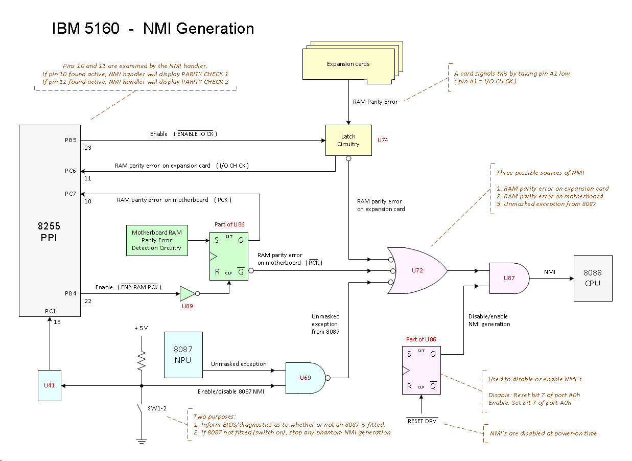
| "RAM parity error latches" | Reference diagrams are at: IBM 5150: here. IBM 5160: here. Step 1: Clear and disable the two 'RAM parity error' latches. Step 2: Verify that neither of the two latches are showing as set. Step 1 is done by setting 8255 pins PB5 and PB4 to HIGH. Step 2 is done by reading the state of 8255 pins PC7 and PC6. |
• Faulty 8255 chip. • IBM 5150: Faulty U52 or U96 or U99. • IBM 5160: Faulty U74 or U86 or U89. • Faulty support chips. See note 1 below. |
| "Check first 2 KB of RAM" | Do a data test of the first 2 KB of RAM. Uses the five test values of: FFh,00h,55h,AAh,01h If this test fails, shown are: • Bit, or bits, in error. <---- If the cause is a faulty RAM chip in RAM bank 0, this indicates which RAM chip. • Address in error. <---- Just in case that is relevant. |
• Faulty RAM chip/s in bank 0. • Incompatible RAM chip/s in bank 0. • RAS/CAS generation circuitry. • ... • ... |
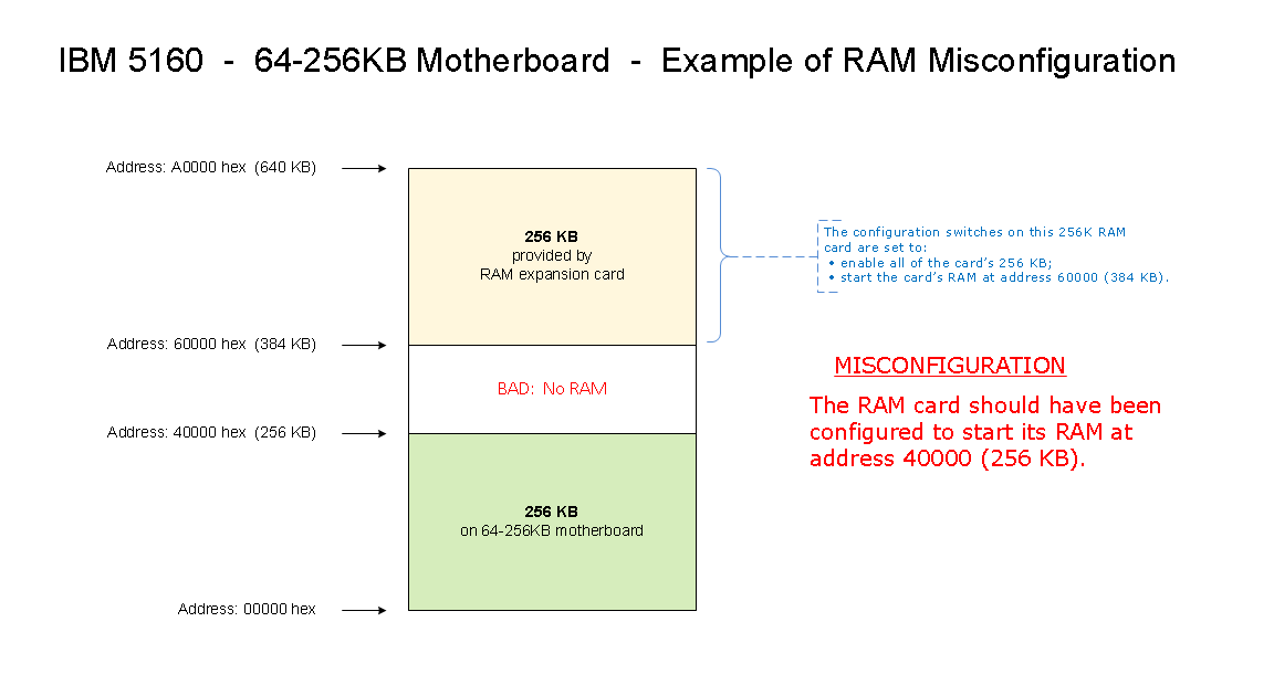
| "Top of RAM:" | Establish where the top of conventional memory (RAM up to 640 KB) is. Basic: Done by starting at address 640 KB, then searching down until RAM is found. More detail: Done by checking one address within each 16 KB sized block. Start with the 16 KB block directly under the 640K (A0000) address. If no RAM found there, check the next lower block. The 'check the next lower block' step is continued until RAM is found. Additional information is in the source code. NOTE: In the misconfiguration shown at here, the diagnostic will report that the 'top of RAM' is 640 KB. Same thing if something goes faulty in a way that creates a gap in RAM. |
|
| "Testing RAM - Data" | Do a data check of the found RAM. Includes the first 2 KB. Uses the same testing technique as the 2 KB RAM test. If this test fails, shown are: • Address in error. <---- If the cause is a faulty RAM chip, this indicates which RAM bank. • Bit, or bits, in error. <---- If the cause is a faulty RAM chip, this indicates which RAM chip. |
• A faulty RAM chip. • Faulty circuitry on motherboard - RAM refresh circuitry. See note 5. • Faulty circuitry on motherboard - Other. |
| "Testing RAM - Address" | Do an address check of the found RAM. Divided into two subtests: 1. The first subtest uses the same code that IBM uses in the IBM 5150/5160. That way we guarantee that Rudd's Diagnostic ROM will detect a RAM addressing problem if the IBM BIOS ROM did. 2. Divide all RAM into 1K blocks. At the first address of each block, write a number unique to the block number. Then read back all written bytes, verifying that each one matches with what was written. If this test fails, shown are: • Address in error. <---- If the cause is a faulty RAM chip, this possibly indicates which RAM bank. • Bit, or bits, in error. <---- If the cause is a faulty RAM chip, this possibly indicates which RAM chip. |
• A faulty RAM chip (faulty in addressing, not data). • A RAM chip with an address pin bent up underneath its body, or a RAM chip with a missing address pin. • A RAM chip that has a poor connection to its socket (on the address pins). • Faulty addressing circuitry on motherboard. |
| "Testing RAM - Refresh" | What we are doing here is checking that the RAM refresh circuitry is functioning. Verify that test values written to RAM are not damaged when they are read back 90 seconds later. SUBTEST 2 of the previous test had written a unique block number to the first address of each 1K sized block. This test takes advantage of that. Step 1: Wait 90 seconds. Step 2: Verify that the unique block numbers written by SUBTEST 2 are still intact. If this test fails, the address in error is shown. NOTE: The period of 90 seconds is based on an IBM 5160 motherboard of mine, that with refresh disabled, will hold RAM contents for between 60 and 70 seconds. |
• Faulty RAM refresh circuitry. • A faulty RAM chip (faulty in a particular way). |
| "Testing RAM - Slow Refresh" | Do a slow refresh check of the found RAM. This is the same as the slow refresh test in the Supersoft/Landmark Diagnostic ROM. Have a read of the 'Slow-Refresh Memory Test' section on page 34 of the manual at here. The slow refresh test seems to be a bit of a: Show any RAM chip 'weaklings' (weak at holding charge). Within spec, but they could be the cause of an intermittent RAM problem (e.g. intermittent PARITY CHECK error). Specifically, this test does the following: Step 1: Set timer 1 to a period of 2 ms. Step 2: Fill the found RAM with 55h. Step 3: Wait 10 seconds. Step 4: Read back was what written, expecting 55h. If something other than 55h is found (anywhere), fail the test. Step 5: Fill the found RAM with AAh. Step 6: Wait 10 seconds. Step 7: Read back was what written, expecting AAh. If something other than AAh is found (anywhere), fail the test. Step 8: Restore timer 1 back to a period of 15 us (normal operation). If this test fails, shown are: • Address in error. <---- If the cause is a faulty RAM chip, this indicates which RAM bank. • Bit, or bits, in error. <---- If the cause is a faulty RAM chip, this indicates which RAM chip. |
• A 'weak at holding charge' RAM chip. |
| "8259 interrupt controller" | Step 1: Initialise the 8259 interrupt controller chip. Step 2: Do a check of the 8259's In-Service Register (ISR). Step 3: Do a check of the 8259's Interrupt Enable Register (interrupt mask register). NOTE: At the end of this test, all hardware interrupts (IRQ0 to IRQ7) are masked out in the 8259. |
• Faulty 8259 interrupt controller chip. • Faulty chip that supports 8259 operation. See note 1 below. |
| "Hot IRQ interrupts" | In the period of about a second, see if a hardware interrupt (IRQ0 to IRQ7) occurs. None is expected. | |
| "Checking interrupt IRQ0" | Reference diagrams are at: IBM 5150: here and here. IBM 5160: here and here. This test varies the output of channel 0 of the 8253, monitoring the 8259 responding to IRQ0, seeing whether IRQ0 is happening too frequently or too infrequently. Of note, the diagnostic puts the 8253 into mode 0 to do that. The IBM BIOS uses mode 3 for channel 0 of the 8253. |
• Faulty circuitry, that shown in the reference diagrams. • Missing 1.193 MHz clock for the 8253 timer chip. • Faulty support chips. See note 1 below. |
| "Hot NMI" | Reference diagrams are at: IBM 5150: here. IBM 5160: here. For a period of about 2 seconds, via I/O port A0h, enable NMI's to reach the 8088 CPU. No NMI's are expected. If an NMI is seen, fail the test. |
• Faulty 8088 CPU. • IBM 5150: Faulty U96 or U97. • IBM 5160: Faulty U86 or U87. • 8087 math coprocessor chip is absent and you have switch 2 in switch block SW1 in the wrong position for that (off). |
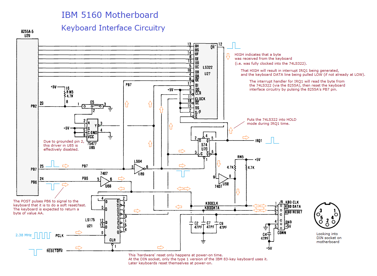
| "Keyboard responds to reset" | Reference diagrams are at: IBM 5150: here and here. IBM 5160: here and here. Via the motherboard's keyboard interface circuitry, soft resets the keyboard. Looks to see if the keyboard then responds to that with the expected byte of AA. NOTE: PC's and XT's require an XT-class keyboard. An AT-class keyboard will not work (unless it supports both XT and AT keyboard protocols). |
• Faulty 'keyboard interface circuitry' on motherboard. • No keyboard. • Faulty keyboard. • Incompatible keyboard. |
| "Keyboard stuck key" | Looks to see if the keyboard is indicating a stuck key. If a stuck key is indicated: - The test fails; and - "Stuck key found:" is displayed, with the reported stuck key (in the form of a byte) displayed to the right of that. NOTE: This test is not performed if the 'Keyboard responds to reset' test failed. NOTE: To work out the actual key, you need to look in the technical reference for the keyboard layout diagram that matches your keyboard. That diagram shows the byte for each key. NOTE: Sometimes a faulty keyboard indicates a stuck key, but the problem is not a stuck key, it is something else. |
• Faulty keyboard. |
| "Check floppy controller" | Sees if the floppy disk controller (FDC) card can be successfully reset. NOTE: For this test, no floppy drive needs to be connected to the controller. |
• Faulty floppy controller card. • Faulty ISA slot. |
| "Trying to read a floppy" | Step 1: Recalibrate. (If not at cylinder 0, move there.) Step 2: Seek to cylinder 5. Step 3: Read 9 sectors from head 0 on cylinder 0. Three attempts made. NOTE: 360K drive and floppy required. NOTE: This test is not performed if the 'Check floppy controller' test failed. |
• Faulty/misaligned 360K floppy drive. • Faulty 360K floppy. • Faulty/incorrect floppy cable. • Incorrectly configured 360K floppy drive. |
| "Check ROM at F4000" | A reference diagram is at here. What this test does is read all of the bytes in the 8 KB sized memory space of F4000 to F5FFF, and then examine them. The test will fail if either of the following two conditions is found: 1. The 8-bit checksum of the bytes is not 00; or 2. All of the bytes in the ROM are the same byte, and that byte is FC, FD, FE, or FF. Such a condition suggests an empty ROM socket. See note 4 below. |
IBM 5150: Normally fails because there is no ROM in socket U28. IBM 5160: Corrupt/damaged BIOS ROM in socket U19. |
| "Check ROM at F6000" | A reference diagram is at here. What this test does is read all of the bytes in the 8 KB sized memory space of F6000 to F7FFF, and then examine them. The test will fail if either of the following two conditions is found: 1. The 8-bit checksum of the bytes is not 00; or 2. All of the bytes in the ROM are the same byte, and that byte is FC, FD, FE, or FF. Such a condition suggests an empty ROM socket. See note 4 below. |
IBM 5150: Corrupt/damaged BASIC ROM in socket U29. IBM 5160: Corrupt/damaged BIOS ROM in socket U19. |
| "Check ROM at F8000" | A reference diagram is at here. What this test does is read all of the bytes in the 8 KB sized memory space of F8000 to F9FFF, and then examine them. The test will fail if either of the following two conditions is found: 1. The 8-bit checksum of the bytes is not 00; or 2. All of the bytes in the ROM are the same byte, and that byte is FC, FD, FE, or FF. Such a condition suggests an empty ROM socket. See note 4 below. |
IBM 5150: Corrupt/damaged BASIC ROM in socket U30. IBM 5160: See note 3 below. |
| "Check ROM at FA000" | A reference diagram is at here. What this test does is read all of the bytes in the 8 KB sized memory space of FA000 to FBFFF, and then examine them. The test will fail if either of the following two conditions is found: 1. The 8-bit checksum of the bytes is not 00; or 2. All of the bytes in the ROM are the same byte, and that byte is FC, FD, FE, or FF. Such a condition suggests an empty ROM socket. See note 4 below. |
IBM 5150: Corrupt/damaged BASIC ROM in socket U31. IBM 5160: See note 3 below. |
| "Check ROM at FC000" | A reference diagram is at here. What this test does is read all of the bytes in the 8 KB sized memory space of FC000 to FDFFF, and then examine them. The test will fail if either of the following two conditions is found: 1. The 8-bit checksum of the bytes is not 00; or 2. All of the bytes in the ROM are the same byte, and that byte is FC, FD, FE, or FF. Such a condition suggests an empty ROM socket. See note 4 below. |
IBM 5150: Corrupt/damaged BASIC ROM in socket U32. IBM 5160: See note 3 below. |
| Note 1 | E.g. If applicable, chips that are involved in the generation of the CHIP SELECT (CHIP ENABLE) signal for the target chip. |
| Note 2 | Given that the CPU tests ran successfully before this test, it seems unlikely. But the ROM --> CPU data path can be tested: IBM 5150: Run TEST5000 at here. IBM 5160: Run TEST6000 at here. |
| Note 3 | IBM 5160. See the right side of the diagram at here. Either: - The 32 KB sized Ruud's Diagnostic ROM is not four copies of the code; or - The 32 KB sized Ruud's Diagnostic ROM is four copies of the code, but a copy is corrupt. - Partially faulty ROM/EPROM used for Ruud's Diagnostic ROM - Bent pin. - Partially faulty ROM/EPROM used for Ruud's Diagnostic ROM - Internally faulty. - An addressing problem on the motherboard. |
| Note 4 | To detect an empty ROM socket, simply seeing if all bytes are the same does not work all of the time. For example, if the diagnostic was to use that methodology, the F4000 ROM check would fail if an IBM 62X0819 ROM is in socket U19 of the IBM 5160 motherboard. That ROM, 32 KB sized, has the byte of CC in the area that maps to motherboard address F4000 to F5FFF. |
| Note 5 | Once, as an experiment, I disabled the RAM refresh circuitry on one of my fully functional IBM 5160 motherboards. The 'Testing RAM - Data' test failed, pointing to four RAM chips in the fourth bank. Those four were four of the five Toshiba TMM4164AP-15 chips on the motherboard. I replaced those chips with other chips, which allowed the 'Testing RAM - Data' to pass. Then as expected, the 'Testing RAM - Refresh' test failed. |